Vacuum Pump and Solenoid Actuation on an OpenPnP Machine
OpenPnP has no concept of a vacuum pump. The pump and the nozzle valve are Boolean actuators, and the software's whole job is sending the text you typed into Machine Setup. On a Vertex 4 the two nozzle actuators are named VAC1 and VAC2, and each one holds two G-code lines rather than one.
The factory configuration Opulo publishes in the LumenPnP repository (openpnp/machine.xml) sends this:
VAC1   True:   M106 P1 S180
                M106
       False:  M107 P1
                M107

VAC2   True:   M106 P2 S255
                M106 P3 S180
       False:  M107 P2
                M107 P3
Both lines of a command go out as one actuation, in file order. The order matters on the wire: on VAC1 the valve line runs first and the pump line second, so the valve is open before the pump starts pulling.
Which output each fan index drives
Opulo's wiring table pairs the cable labeled P1 with the motherboard port labeled MOS1, and the unlabeled valve cable with MOS2. Their actuator test page names the outputs the same way: M106 turns MOS1 on, which is the vacuum pump; M106 P1 S255 / M107 P1 is the blow-off valve on MOS2; and MOS3 and MOS4 answer to P2 and P3 when something is plugged into those ports.
The firmware side is a count of pins. In pins_OPULO_LUMEN_REV4.h:
#define FAN0_PIN   PE2
#define FAN1_PIN   PE3
#define FAN2_PIN   PE4
#define FAN3_PIN   PE5

#define FAN_SOFT_PWM_REQUIRED
Marlin takes FAN_COUNT from the highest fan pin the board defines (four, once HAS_FAN3 is set), and the Opulo REV4 Configuration.h leaves NUM_M106_FANS commented out, so all four outputs stay addressable from G-code. A fan index is therefore a board output number and has nothing to do with which nozzle is using it. VAC1 drives MOS2 on its first line and MOS1 on its second; VAC2 drives MOS3 and MOS4.

S180 and S255 are duty cycles, and the output is soft-PWM
The speed in M106 is a duty cycle: 255 is 100%, 128 is 50%, and M106 with no speed sets full. These fan outputs are not hardware PWM. The Opulo REV4 configuration defines FAN_SOFT_PWM, SOFT_PWM_SCALE is 0, and Marlin's own comment on that setting says it leaves 128 effective control positions (temperature.cpp lists the resulting frequency: 16000000/64/256/128 = 7.6294 Hz).
One period is about 131 ms, and the on-time the firmware generates lands near speed/256 of that window. A speed of 180 holds the output on for roughly 92 ms and releases it for 39 ms, five and a half times a second. A speed below 255 therefore interrupts the coil for part of every period, and the ring lights are not on this list at all: they answer to M150 instead, as the camera lighting page covers.
Our FAQ documents what that looks like on a stock config: the pump and valves test fine on the debug page, and the valve stays shut during a job, because the actuator line reads 180 where the hardware needs 255. The fix is Machine Setup → Actuators → VAC1 and VAC2, changing S180 to S255.
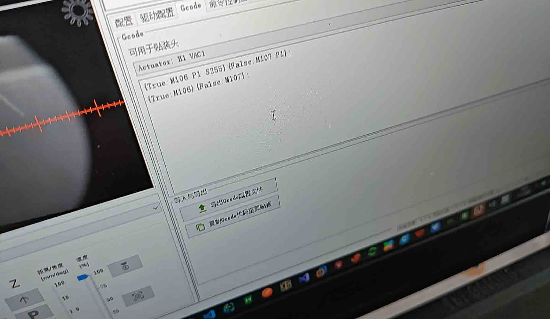
Two lines carry 180 in the factory file and they sit on different fan indices (VAC1's first line on P1, VAC2's second on P3), which is why the instruction names both actuators.
The 180 is a value in a configuration file, which is why a stock file brings it back. The JUKI variants on the downloads page ship with the correction applied and with the nozzle tip calibration data; that is also why the OpenPnP configuration comparison treats both of the faults this machine reports as configuration problems that present as hardware.
An index out of range fails without a message
M106 and M107 in Marlin 2.1 read the fan index with parser.byteval('P', ...) and return early when it is at or past the count:
if (pfan >= _CNT_P) return;
Nothing goes back over the serial link, so M106 P4 S255 on this board is a no-op you can spend an afternoon on. A plain M106 resolves to index 0, which is the pump here, and M107 with no P turns off the same output. Where only one fan is addressable, which happens when NUM_M106_FANS 1 is set, P1 through P3 all land in that silent early return.
The M42 pulse in the driver list that cannot fire
The same driver block carries a second kind of actuation, a raw pin pulse:
M42 P35 S255
G4 P{True:100}{False:200}
M42 P35 S0
M42 writes a pin number directly and Marlin only compiles it under DIRECT_PIN_CONTROL, which is commented out in the Opulo REV4 Configuration_adv.h. Without that define the case 42 entry is absent from the command table in gcode.cpp, so the firmware treats the line as unknown and answers with its parser warning. Nine of the actuator ids referenced in that driver's command list have no matching actuator anywhere in the file, including the one that owns this pulse, so nothing in the OpenPnP interface sends it either.
Enable the define and two behaviours in M42.cpp are worth having in mind: a pin that is also a part-cooling fan pin writes the fan speed instead of the pin state, and a write to an input pin answers Cannot write to INPUT.
Reading the line when the machine has no pressure sensor
A Vertex 4 ships without a pressure sensor, which is why pick verification runs through the bottom camera instead of a pressure threshold. The actuator read commands are still in the factory config, and they are the cheapest way to watch the pneumatics move:
M260 A112 B1 S1 ; select VAC1 through the multiplexer
M260 A109 B6 S1 ; select the register
M261 A109 B1 S2 ; request one byte back
with ^.*data:(?<Value>.*) as the reply regex. Machine Controls → Actuators → Read runs that sequence with every vacuum gate switched off, which is what you want while collecting readings.
Opulo's actuator test page uses the other available path, M3426 G4 C1 I1 A110, and expects the number to move by about 200 when you cover the tip with a finger and turn the pump on (about 2000 with the interposer boards and G2 in place of G4). M3426 is compiled behind HAS_MCP3426_ADC, a define the REV4 pins file carries, so both read paths exist on this hardware. Sensor addresses vary by batch; the page suggests stepping addresses 0 through 7 if A110 returns nothing.
Order of checks for a nozzle with no vacuum
- Actuate the nozzle actuator from Machine Controls and listen. A click is the valve, a hum is the pump. If you get both and still no suction, the fault is downstream at the tip.
- Read the command text in Machine Setup → Actuators. A 180 on a line that has to hold a valve open is the first thing to change, and the JUKI configs already have it at 255.
- Check the index.
P0throughP3exist on this board. Anything higher is dropped in silence. - Work upstream if the command is correct: tubing from the pump to the valve, the Y splitter, then the tip. Our solenoid write-up covers the electrical checks at the valve itself.
- Re-test from the actuator panel after every edit. The ON and OFF branches are separate lines, so a change to one leaves the other in its previous state.
The actuators also carry coordination settings in that same file. They are version 1.1 objects with the enum form of the switches (coordinated-before-actuate-enum="WaitForStillstand", coordinated-after-actuate-enum="None"), the defaults OpenPnP applies when it upgrades a 1.0 machine file on load. WaitForStillstand is what keeps the valve from opening while an axis is still moving.